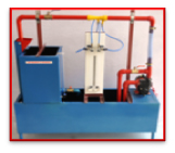
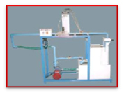
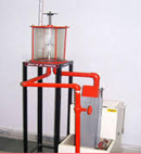
1. Venturimeters Apparatus
Venturimeter is a device used to measure the flow in a pipe. This apparatus is used to determine the
coefficient of discharge. The system is closed circuit.
The apparatus consists of:
• A Centrifugal pump of 25mm x 25mm with 1/2 HP Motor (ISI – Kirlosker Make)
• M.S. Sump Tank 80 Ltr. to collect the water.
• M.S. Measuring Tank 30Ltr fitted with piezometer tube to measure the discharge. Damper is used to
collect the water in M.S. MEASURING TANK for certain time.
• G.I. pipe of internal dia 25mm and Gunmetal ISI mark Control Valve and regulating valves are used to
circulate water.
• Bye-pass line is also used to regulate the discharge. This apparatus consists of
metallic/venturimeter. The openings from inlet and throat are connected to U tube mercury manometer to
measure the head difference. The tanks are well FRC fiber coated insidedto prevent rust hence increase
the life of tank.
Experimental capability:
• To determine the efficiency of discharge for a Venturimeter.
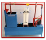
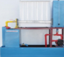
2. Orifice Meter Apparatus
Orifice meter is a device used to measure the flow in a pipe. This apparatus is used to determine the
coefficient of discharge coefficient of velocity. The system is closed circuit.
The apparatus consists of:
• A Centrifugal pump of 25mm x 25mm with 1/2 HP Motor (ISI – Kirlosker Make)
• M.S. Sump Tank 80 Ltr. to collect the water.
• M.S. Measuring Tank 30 Ltr fitted with piezometer tube to measure the discharge. Damper is used to
collect the water in M.S. MEASURING TANK for certain time.
• G.I. pipe of internal dia 25and Gunmetal ISI mark Control Valve and regulating valves are used to
circulate water.
• Bye-pass line is also used to regulate the discharge. This apparatus consists of a metallic orifice
meter. The pressure tapping from U/S side and D/S side is connected to the U Tube mercury manometer to
measure head difference.The tanks are well FRC fiber coated insided to prevent rust hence increase the
life of tank.
Experimental capability:
• To determine the efficiency of discharge for an Orificemeter.
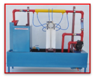
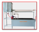
3. Minor Losses in Pipes and Pipe
A liquid flowing through a pipe will experience energy losses due to viscous resistance. The system is
closed circuit. This apparatus is used to measure the losses due to :
• Sudden Enlargement
• Sudden Contraction
The apparatus consists of:
• A Centrifugal pump of 25mm x 25mm with 1/2 HP Motor (ISI – Kirlosker Make)
• M.S. Sump Tank 80 Ltr. to collect the water.
• M.S. Measuring Tank 30 Ltr fitted with piezometer tube to measure the discharge. Damper is used to
collect the water in M.S. MEASURING TANK for certain time.
• G.I. pipe of internal dia 25mm and Gunmetal ISI mark Control Valve and regulating valves are used to
circulate water.
• Bye-pass line is also used to regulate the discharge.
This apparatus consists of:
• Large bend made up of G.I.
• Sudden enlargement from 25mm dia to 32mm dia.
• Sudden contraction from 32mm dia to 25mm.
• Gunmetal gate valve of 25mm dia. A U tube manometer is connected to pet cock through plastic tubing to
measure head difference. The tanks are well FRC fiber coated inside to prevent rust hence increase the
life of tank.
Experimental capability:
• To determine the loss coefficient for different type of fittings.
• Comparison of pressure drops across two different types.
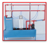
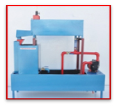
4. Pipe Friction Apparatus
This apparatus is used to measure Darcy's friction coefficient (F) for given pipes.
• The system is closed circuit.
The apparatus consists of:
• A Centrifugal pump of 25mm x 25mm with 1/2 HP Motor (ISI – Kirlosker Make)
• M.S. Sump Tank 80Ltr. to collect the water.
• M.S. Measuring Tank 30 Ltr fitted with piezometer tube o measure the discharge. Damper is used to
collect the water in M.S. MEASURING TANK for certain time.
• G.I. pipe of internal dia 25mm and Gunmetal ISI mark Control Valve and regulating valves are used to
circulate water.
• Bye-pass line is also used to regulate the discharge.
This apparatus consists of a three G.I. pipe 15mm &20mm. The pressure tapings are provided 100cm apart
on each pipe. Each tapings are connected to the mercury U Tube Manometer to measure head difference.
Hand shuts valves are provided on each pipe to open supply in the pipe.The tanks are well FRC fiber
coated insidedto prevent rust hence increase the life of tank.
Experimental capability:
• To determine the loss coefficient for different type of fittings.
• Comparison of pressure across two different types.
5. Pitot tube Apparatus
This apparatus is used to measure the velocity of fluid in the pipe. This apparatus is also used to
measure the coefficient of pitot tube. The system is closed circuit. The apparatus consists of:
The apparatus consists of:
• A Centrifugal pump of 25mm x 25mm with 1/2 HP Motor (ISI – Kirlosker Make)
• M.S. Sump Tank 80 Ltr. to collect the water.
• M.S. Measuring Tank 30 Ltr fitted with piezometer tube to measure the discharge. Damper is used to
collect the water in M.S. MEASURING TANK for certain time.
• G.I. pipe of internal dia 25mm and Gunmetal ISI mark Control Valve and regulating valves are used to
circulate water.
• Bye-pass line is also used to regulate the discharge.
The apparatus consists of:
• Brass pitot tube (bend through 90o) fitted 1" pipe. Pressure tapings are provided on pitot tube and
pipe. The pressure tapping are connected to the inclined U Tube Mercury Manometer to measure pressure
difference. The tanks are well FRC fiber coated insided to prevent rust hence increase the life of tank.
6. Bernoulli's Theorem Apparatus
The apparatus is used to verify the Bernoulli's Theorem.
The system is closed circuit.
The apparatus consists of:
• A Centrifugal pump of 25mm x 25mm with 1/2 HP Motor (ISI – Kirlosker Make)
• M.S. Sump Tank 80 Ltr. to collect the water.
• M.S. Measuring Tank 30 Ltr fitted with piezometer tube to measure the discharge. Damper is used to
collect the water in M.S. MEASURING TANK for certain time.
• G.I. pipe of internal dia 25mm and Gunmetal ISI mark Control Valve and regulating valves are
used to circulate water.
• Bye-pass line is also used to regulate the discharge.
• The apparatus consists of a variable area duct of perpex sheets with eleven piezometer, 7 tube (50cm
height) fitted at equal distance. The duct is connected in between inlet and outlet tanks of size 25x 25
x 60cm each.The tanks are well fiber coated inside to prevent rust hence increase the life of tank.
Experimental capability:
• To verify the Bernoulli's Theorem experimentally.
7. Reynolds Apparatus
The apparatus consists of:
To visualize different flow conditions i.e.
• Laminar flow,
• Transition flow,
• Turbulent flow
To find out the Reynolds number
The system is closed circuit. The apparatus consists of :
• A Centrifugal pump of 25mm x 25mm with 1/2 HP Motor (ISI – Kirlosker Make)
• M.S. Sump Tank 80 Ltr. to collect the water.
• M.S. Measuring Tank 30 Ltr fitted with piezometer tube to measure the discharge. Damper is used to
collect the water in M.S. MEASURING TANK for certain time.
• G.I. pipe of internal dia 25mm and G.M. ISI mark Control Valve and regulating valves are used to
circulate water.
• Bye-pass line is also used to regulate the discharge. This apparatus consists of a Perspex tube of
internal dia12mm dia x 80cm long. A needle and color dye injector tank is used to visualize the flow &
tanks of size 25x 25 x 60cm each. The tanks are well FRC fiber coated insidedto prevent rust hence
increase the life of tank.
Experimental capability:
• To visualize different flow conditions.
• To obtain the critical velocity.
8. Triangular and Rectangular Notch Apparatus
Notches are openings cut in metallic plates are used for the purpose of measuring the discharge in
stream. This apparatus is used to measure the coefficient of discharge of notches of various shapes.
• The system is closed circuit:-
V - Notch of angle 60o
Rectangular Notch of 100x100mm
The apparatus consists of:
• A Centrifugal pump of 25mm x 25mm with 1/2 HP Motor (ISI – Kirlosker Make)
• M.S. Sump Tank 80 Ltr. to collect the water.
• M.S. Measuring Tank 30 Ltr fitted with piezometer tube to measure the discharge. Damper is used to
collect the water in M. S. Measuring Tank for certain time.
• G.I. pipe of internal dia 25mm and Gunmetal ISI mark Control Valve and regulating valves are used to
circulate water.
• Bye-pass line is also used to regulate the discharge.
• This apparatus consists of a rectangular tank of
80x25x25cm with rectangular opening at one end on which rectangular or V-Notch can be fitted with
nuts.
• A pointer scale is used to measure the level of water in the tank. The tanks are well FRC fiber coated
inside to prevent rust hence increase the life of tank.
Experimental capability:
Determination of coefficient of discharge of:
60oC notch,
Rectangular notch100x100mm
9. Impact of Jet Apparatus
This apparatus is used to verify the momentum equation experimentally. This is also used for comparison
of change in force exerted due to shape of the vane for different targets (Flat or curved). The system
is closed circuit.
The apparatus consists of:
• A Centrifugal pump of 25mm x 25mm with 1/2 HP Motor (ISI – Kirlosker Make)
• M.S. Sump Tank 80 Ltr. to collect the water.
• M.S. Measuring Tank 30 Ltr fitted with piezometer tube to measure the discharge. Damper is used to
collect the water in M.S. MEASURING TANK for certain time.
• G.I. pipe of internal dia 25 mm and Gunmetal ISI mark Control Valve and regulating valves are us This
apparatus is used to verify the momentum Equation experimentally. This is also used for comparison of
change in force exerted due to shape of the vane for different targets(Flat or curved).
• Bye-pass line is also used to regulate the discharge.
• This apparatus consists of
a Perspex cylinder of 150mm dia with two interchangeable targets
(curved and
plane). A nozzle of 10mm is fitted to produce jet. A scale is provided on the top to measure the
displacement of plate. Five additional weights of 100 gm. each are also provided.The tanks are well FRC
fiber coated insidedto prevent rust hence increase the life of tank.
Experimental capability:
To verify the momentum equation experimentally.
Comparison of change in force exerted due to shape of the vane for different targets (flat or curved) to
circulate water.
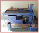
10. Hydraulic Test Bench
Hydrauliv Bench with necessary accessories forms a needful laboratory facility which enables to perform
various Fluid Mechanics experiments.
The apparatus consists of:
• A Centrifugal pump of 25mm x 25mm with 1/2 HP Motor (ISI – Kirlosker Make)
• M.S. SUMP TANK 80 Liter to collect the water.
• M.S. angle frame 200 x 90 x 90 cmmounted on four wheels for easy movement
• M.S. MEASURING TANK 30 Liter fitted with piezometer tube to measure the discharge. Damper is used to
collect the water in M.S. MEASURING TANK for certain time.
• G.I. pipe of internal dia 25 mm and ISI mark control valve and regulating valves are used o circulate
water.
• Bye-pass line is also used to regulate the discharge.
Following apparatus are provided with this bench:
→ Bernoulli's Theorem Apparatus
• Flow measurement by Venturimeter
• Flow measurement by Orifices meter
• Notch Apparatus
• Losses in Pipe Fitting Apparatus.
• Pipe Friction Apparatus
• Reynolds Apparatus.